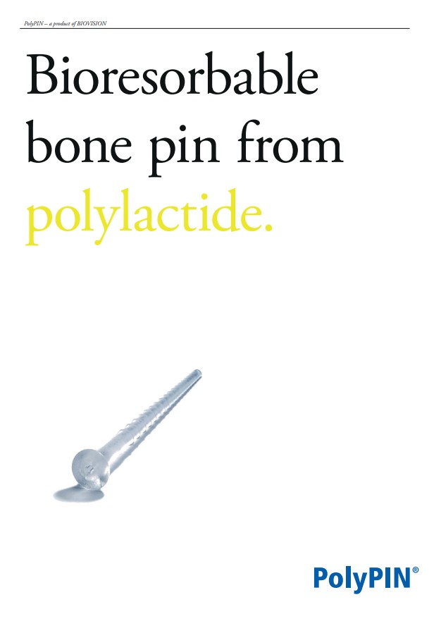
PolyPIN

PolyPIN is a bioresorbable bone pin from polylactide. Metal implants are normally removed in a second operation, once the bone has healed.
This not only means additional expense, but is also stressful for the patient!
What is more, a second stay in hospital is necessary to remove the metal, involving absence from work and increased risk of complications.
The ideal osteosynthesis implant should, therefore, simply dissolve after it has fulfilled its stabilising or fixing task, without subjecting the body to an additional burden in doing so. The Polypin is such an implant.
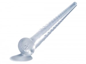
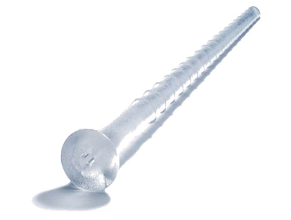
It is a pin made of a polylactide copolymer (Poly L/D, L- Lactide 70/30). Thanks to the material it is made of and the way it is designed, it offers significant advantages.
Indications
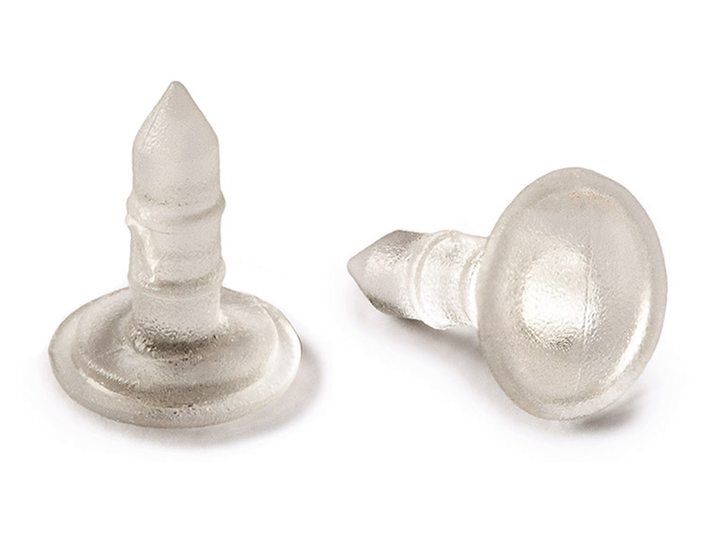
The PolyPIN special design is its distinguishing feature and improves its performance:
The head exerts a slight compression on the facture fragments.
The circular ribs prevent the PolyPIN from slipping.
The Polypin is available in three different diameters:
- PolyPIN 1.5, length: 8 – 25 mm
- PolyPIN 2.0, length: 10 – 35 mm
- PolyPIN 2.7, length: 12 – 60 mm


Fractures subject to low load stresses: PolyPIN 1.5
Fixation
of bony or osteochondral fragments: e.g. fractures to the heads of
metacarpal bones, arthrodeses of fingers and toes, stabilising of
certain finger factures, osteochondral factures or dissections
eochondral fractures or dissections.
Apical fragements, osteochondral fractures or dissections: PolyPIN 2.0
Apical
fragments: e.g. fractures of the radial head, fracture of the patella
rim, fractures at the proximal and distal ends of the metatarsal and
metacarpal bones.
Osteochondral fractures or dissections:
e.g. ankle-bone dome, femoral
condyle, cancellous fragments or those subject to low stresses: e.g.
layered reconstruction of fractures of the heel or acetabulum,
corticocancellous grafting of chips.
Large osteochondral fragments: PolyPIN 2.7
Large osteochondral fragments: e.g. fractures of the femur head (Pipkin
fractures), fractures of the malleolus (Weber A fractures), fractures of
the radius, longitudinal fractures of the patella.
Material / Effect
The PolyPIN is made of polylactide, an absorbable biomaterial which has proved its worth as a material for biological implants, as shown by extensive in vitro an in vivo testing an in clinical use over several years. The special copolymer (Poly L/D, L- Lactide 70/30) has good absorption properties:
Its flexural strength remains constant for 24 weeks, which is a sufficient time for the fracture to heal, and then drops at a constant rate.
Degradation
Biological degradation takes place mainly due to hydrolysis, into lactic acid, which is a natural product of metabolism, and is subsequently metabolised into CO2 and H2O. Within 15 months the Polypin is completely degraded from a mechanical point of view, although it can still be detected in the form of a cylindrical fragment of the original pin.
After 18 to 21 month only fibrous cords are recognisable and
after another three months the place of implant is filled with bony
substance. Studies have shown that the same results are achieved both by
the Polypin and a metal implant, but in the case of the Polypin no
implantdependent complications arise.
Design
The PolyPIN special design is its distinguishing feature and improves its performance:
- The head exerts a slight compression on the facture fragments
- Circular ribs prevent the PolyPIN from slipping
The Polypin is available in three different diameters:
- 1.5 mm PolyPIN, length: 8 - 25 mm
- 2.0 mm PolyPIN, length 10 - 35 mm
- 2.7 mm PolyPIN, length: 12 - 60 mm
Application
Drilling
After reducing the fragments, drill a hole of the same diameter as the PolyPIN.
- Diameter 1,5 mm for the PolyPIN 1.5
- Diameter 2,0 mm for the PolyPIN 2.0
- Diameter 2,7 mm for the PolyPIN 2.7
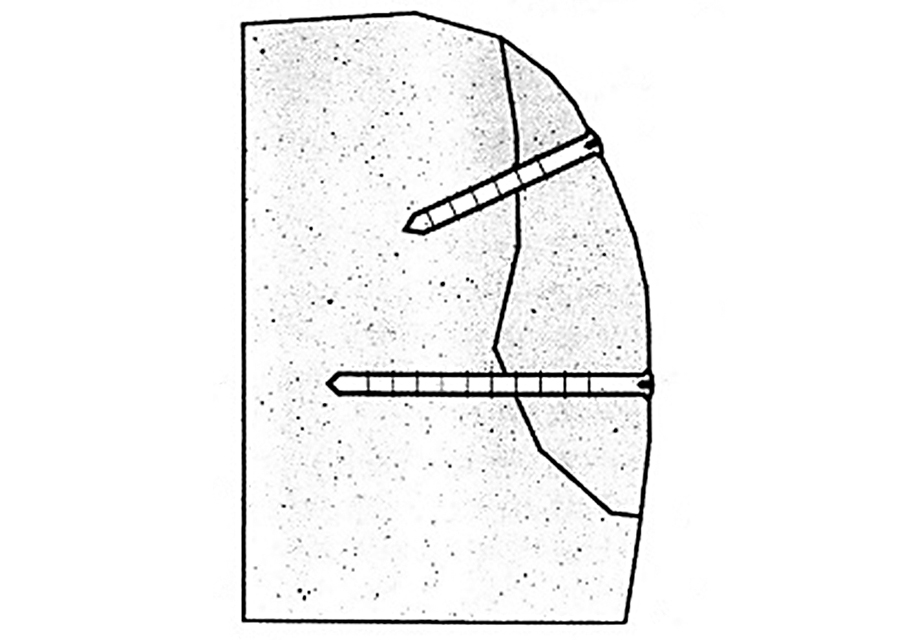
perpendicular to the surface of the fracture. If more than one
PolyPIN is used, the drilled holes should not run parallel, but
converge, to ensure secure fixation of the fragment.
Length measurement
After
loosening the locking screw, insert the measuring tip of the
appropriate depth gauge as far as possible to the end of the drilled
hole. The depth of the drilled channel can then be determined.
Tighten the locking screw. In this way, the measured length is
transferred directly to the cutting guide secured at the rear. The
PolyPIN is then sheared to about 1 mm less than the measured drilling
depth
Shortening the PolyPIN
Push
the PolyPIN head first as far as the stopper in the mounting at the
rear end of the measuring device. Secure by means of the locking screw.
Position the shearing head so that the arrow marked on it is visible.
Turn the shearing head in the direction of the arrow to shear the PolyPIN to the requiered length.
WARNING: Do not turn the shearing head in the opposite direction
to the arrow. This could press the PolyPIN against the locking screw and
cause
deformations.
Adjusting the tip of the PolyPIN
Adjust
the pin using the sharpener to simplify insertion. Once the cut – off
part has been removed, withdraw the pin sligthly from the depth gauge
and then secure again by means of the locking screw. Then adjust
sligthly using the sharpener as you would a pencil sharpener.
Impacting the PolyPIN
The
respective special impacting device and a hammer must be used to insert
the PolyPIN. Remove the pin from the impactor and insert the PolyPIN
tip first into the casing from the rear. Insert the pin again and push
it forwards slowly until the tip of the PolyPIN into the drilled hole
and place the impacting device over the hole, perpendicular to the
fragment surface. Make sure that the PolyPIN does not become jammed
while it is being hammered in. Then carefully hammer the PolyPIN into
the drilled channel until the head is below the level of the surface of
the fragment.
WARNING: Oblique positioning may cause the impacting device to
slip resulting in the PolyPIN being broken and the white cap for the
impacting
device damaged.
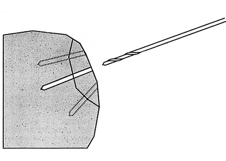 Figure 1: Drilling
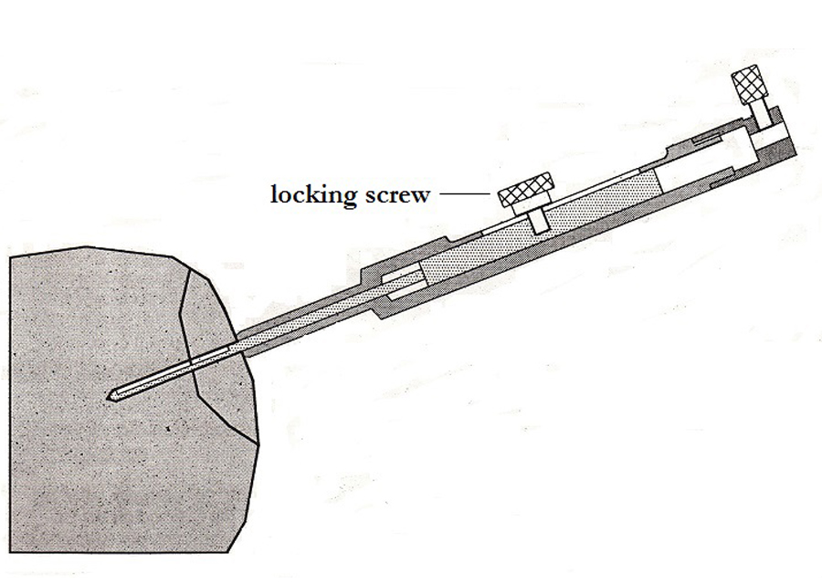 Figure 2: Length measurement
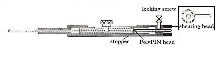 Figure 3: Shortening
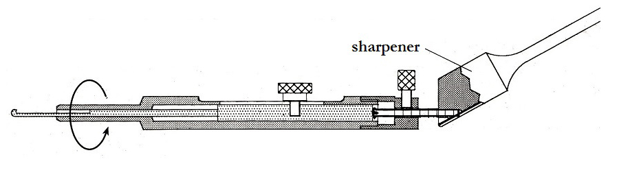 Figure 4: Adjusting the tip
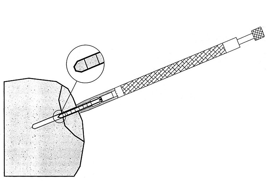 Figure 5: Impacting
PolyPIN
EpiGARD